This is another old article from the depths of my hard drive, its going up partially for my own reference as the address space sizes per bit is useful from time to time, and also coz I might as well make it public again, someone may find it useful/interesting too.
Its all about RAM and how it is addressed....
Despite the complexity of the chips themselves the actual way they are used is pretty simple. Every RAM chip has address input lines, and data I/O lines. At this point its worth saying that RAM chips come in different types with different capacity per location. I am working with 8 bit chips predominantly as I am working with an 8 bit system. By 8 bit I mean that every memory location (as defined by the address lines) contains 8 bits - 1 byte. You can get 16 bit chips that hold 16 bits (aka a WORD) per location. They also have a CS (chip select) and a WR (write) line, the last two lines are control signals, in most systems you will have multiple RAM chips sat on the same bus, they will be connected together in a ladder formation on the board, but then can be thought of as piggybacking on top of each other, with the address and data lines all connected. The CS line tells the chip to shutup or to be active, when its told to shut up it turns off its data lines and does not talk on the data bus, clearly you should only have 1 RAM chip active at any given time or you would get confusion on the bus. By bus I just mean the group of 8 data lines, literally just 8 copper tracks that run from the RAM to the CPU.
The address bus comprises of 16 lines from the CPU and these just refer to a certain number, starting with A0 these lines are named A0 to A15.
The addressable memory of a system is not actually tied to the "bit" number of the CPU, i.e. an 8 bit CPU does not necessarily have 8 bits of address space. The Z80 is an 8 bit CPU, but it has a 16 bit address space. With its 16 address lines (A0-A15) it can refer to 65535 distinct memory locations. Think of the address spaces as a binary number - if you have 16 digits, in binary these can be either on or off, the largest decimal number a 16 bit binary number can describe is 65535. Each of these memory locations contains 8 bits, or 1 byte, therefore the Z80 can access a maximum of 65535x8 bits, which is 64KB. To access any larger amount you would need additional address lines, adding 1 more address line (A16 - i.e. the 17th address line) would permit you to address 128KB of RAM if its an 8 bit system. Some early supercomputers actually had 18 bit address spaces which permit you to define enough memory locations for 256KB.
Any 8 bit computer that claims to have more than 64KB is actually using paging, the CPU can only be connected to 64KB at any given time. As the RAM chips share the same data bus - ie the same set of copper tracks to the CPU it is possible to shut them all down bar the single RAM chip that is in use at that time. Usually this is done in 32KB lumps, the lower 32KB remains constantly connected to the CPU (otherwise it would forget what it was doing) and the upper 32KB is swapped in and out as required. As long as only 1 RAM chip is active at any given time the system works. Due to the way binary numbers work and the fact that the system work on electrical voltage states it is possible to use the address line activity to shut down or activate the right chip. If each chip holds a maximum of 32KB then if the 16th address line is high (ie a 1) then you rig up the logic to put the lower 32KB chip in standby, and bring the upper 32KB chip back to life. After all if that address line stays high then the memory it is accessing at that point has to be above 32KB, ie in the upper RAM chip.
Of course even with paging in blocks of RAM the whole 64KB limit was a severe limitation, recently processors have hit the limit of the 32bit address space. Back in 1988 when CPUs moved to a 32bit bus the amount of addressable space seemed beyond anyone's wildest dreams, a whole 4 Gigabytes, memory that would cost more than the price of 2 or 3 houses. Imagine spending 900,000 pounds on RAM today and you get the idea of how impossible it seemed that we would get there, but with only 32 digits that can be 0 or 1 you can only define 4GB of address space. A 32 bit PC will never be able to see more than 4GB of ram, it is blind to anything above that, due to various reasons you wont actually get al whole lot of use out of your 4th GB as the address space is borrowed for other purposes as when the standards were laid down it was thought that there would never be any physical RAM at those address locations.
Some PCs will not support RAM up to 4GB anyway - this is because they chose an upper number when designing the board and didn't etch a full complement of 32 address lines. If they only gave the board 30 lines the max you could ever get the system to see would be 1GB. The fewer address lines the simpler the board can be, the fewer board layers are needed and the cheaper it all becomes to make. The CPU still has a 32bit address space but the system bus only has 30 bits to play with. The Atari ST used a M68000 a 16 bit processor with in-theory a 32 bit bus, in theory the 68000 could address 4GB but the upper 8 bit of the address space were simply ignored when it came to talk to the bus, it only has 24 bits of address space, the CPU would have needed 4 more pins to cope with a full 32bit address space. Ditching the upper byte meant the 68000 could address a maximum of 16MB, but in the ST the memory management unit and the PCB were only wired with 22 address lines, so the max an ST could ever see and use (without modifications involving wires soldered onto the CPU) was 4MB, a shed load of RAM for the time. Spending the money deploying a full 32bit address bus would be money wasted making the board much more complicated to support memory amounts that users would never install.
1 -single byte
11 - 4 bytes
111- 8 bytes
1111- 16 bytes
11111- 32 bytes
111111-64 bytes
1111111-128 bytes
11111111- 256 bytes
111111111-512 bytes
1111111111- 1KB
11111111111- 2KB
111111111111- 4KB
1111111111111- 8KB
11111111111111- 16KB
111111111111111- 32KB
1111111111111111- 64KB
11111111111111111- 128KB
111111111111111111- 256KB
1111111111111111111- 512KB
11111111111111111111- 1MB
111111111111111111111- 2MB
1111111111111111111111- 4MB
11111111111111111111111- 8MB
111111111111111111111111- 16MB
1111111111111111111111111- 32MB
11111111111111111111111111- 64MB
111111111111111111111111111- 128MB
1111111111111111111111111111- 256MB
11111111111111111111111111111-512MB
111111111111111111111111111111- 1GB
1111111111111111111111111111111- 2GB
11111111111111111111111111111111- 4GB
Going to a 64bit address space takes you back in to the realms of insane amounts of RAM, which would again cost you more than a good few houses. 64 bits can define enough ram locations for 16Exabytes of storage. More than we will ever probably see in a home system. People have made claims about that before but this time there is probably a good reason why it will never happen, the fact that people only live for about 80 odd years. Assuming you took HD video of your entire life you would never fill 16EB of storage, and even then if you did amass that amount of data there is no way you would want to store it in a RAM system. Writing it to disk is another matter and doesn't follow the same constraint as its not based on blocks of space defined by large binary patterns. So 16EB is more RAM than you could ever fill, and you would never store that much data in that way anyway. So somewhere between 4GB and the 16EB is the figure of "more than you will ever need".
Modern 64bit PC motherboards so not have 64 address lines anyway, its pointless to design it that way. By the time that amount of RAM becomes a viable option the motherboard would have been landfill for well over a decade. The board would be significantly more difficult and expensive to make and no one would ever benefit. You can safely assume that if a modern PC board will take say 16GB of RAM, then only 34 address lines have been designed and laid out.
In fact the current 64bit CPUs don't even bother with the fully 64bit address space, the AMD Athlon X2 only has 40 address lines, the max this chip will every be able to address is 1TB, again that's more than the chip is ever likely to see in its lifetime. Even internally it can only understand address ranges that are 48 bit - or 256TB, this is its entire viewable range and applies to virtual as well as physical RAM.
111111111111111111111111111111111- 8GB
1111111111111111111111111111111111- 16GB
11111111111111111111111111111111111- 32GB
111111111111111111111111111111111111- 64GB
1111111111111111111111111111111111111- 128GB
11111111111111111111111111111111111111- 256GB
111111111111111111111111111111111111111- 512GB
1111111111111111111111111111111111111111- 1TB
11111111111111111111111111111111111111111- 2TB
111111111111111111111111111111111111111111- 4TB
1111111111111111111111111111111111111111111- 8TB
11111111111111111111111111111111111111111111- 16TB
111111111111111111111111111111111111111111111- 32TB
1111111111111111111111111111111111111111111111- 64TB
11111111111111111111111111111111111111111111111- 128TB
111111111111111111111111111111111111111111111111- 256TB
1111111111111111111111111111111111111111111111111- 512TB
11111111111111111111111111111111111111111111111111- 1PB
111111111111111111111111111111111111111111111111111- 2PB
1111111111111111111111111111111111111111111111111111- 4PB
11111111111111111111111111111111111111111111111111111- 8PB
111111111111111111111111111111111111111111111111111111- 16PB
1111111111111111111111111111111111111111111111111111111- 32PB
11111111111111111111111111111111111111111111111111111111- 64PB
111111111111111111111111111111111111111111111111111111111- 128PB
1111111111111111111111111111111111111111111111111111111111- 256PB
11111111111111111111111111111111111111111111111111111111111- 512PB
111111111111111111111111111111111111111111111111111111111111- 1EB
1111111111111111111111111111111111111111111111111111111111111- 2EB
11111111111111111111111111111111111111111111111111111111111111- 4EB
111111111111111111111111111111111111111111111111111111111111111- 8EB
1111111111111111111111111111111111111111111111111111111111111111- 16EB
Go towards 128bit/256bit/512bit address spaces and I think you start getting into the realms of more atoms than there are in the solar system, i.e. if every atom in the solar system was made part of a RAM system somehow and each atom represented 1 bit you would run out of atoms to use before you filled the address space, don't take my word for that as I have no plans to count any further. :)
Monday, December 15, 2008
Saturday, December 6, 2008
MSX RAM Upgrade
A few weeks ago I snapped up an MSX machine on eBay, had wanted one for a while but the MSX range of machines is a very wide, and I wanted an interesting one! Well the one I found is probably the most interesting one there ever was. MSX was an 8bit standard set up by a consortium of Japanese companies in the 80s who were trying to create a range of machines which possessed the then-unheard of feature called software compatibility. So at heart all MSX machines are very much alike, its the bolt on extras that differentiate them.
The one I bought was the Yamaha C5XM machine, an MSX 1 standard machine but its bolt on extra was the heart of the top of the range (at the time) Yamaha DX7 Synthesiser. Its got a honking great synth board stashed away inside which is midi compatible and has over 100 built in voices. Of course MSX software cant use that as its not standard so it has a separate ROM for the music application. They are not common tho as they didn't sell well, it was a niche market and at between 500 and 700 quid a go there were not cheap.
Anyway - having got this machine I not only wanted to play around with the synth module, I also wanted to run up some games - mainly Gunfright - my hands down favourite 8 bit game which surprisingly got an outing on the MSX.
I was to be disappointed, my MSX only has 32KB on-board, which is a drop too little to do anything useful these days. The problem is actually two-fold, firstly the fact I don't have much ram, secondly is the way MSX software is presented these days means that 32KB is less useful than it once was.
As MSX machines all had a cartridge slot, the majority of the software available these days for the emulators is in the format of a ROM dump. Even games that were never originally available on ROM have been snap-shotted and saved as binary files. This is great if you have an emulator as you just load the .rom into the systems virtual ROM slot, its also good if you have a spare ROM cart and an eprom blower as you can make a real ROM cart.
As ROMs are useful and neat, it seems all other formats have died a death, I can't find anywhere where you can download MSX software in non-ROM format. You would assume there is a way to turn the old .rom files back into wav files such as there is for many other formats. Well yes and no, spectrum and oric data files are not really ROM files, (snapshots aside), most are actually block patterns that were once on tape, when loaded sequentially the emulator is running the exact same operations that the tape loader of old was doing, only a damn sight faster. A binary ROM file contains no information about how the software was actually loaded, its just a block of information that appears on the data bus, there is no "how to load and where to start" information that was once part of the tape version of the games. These loaders are no more, stripped off by the process of dumping the RAM into a ROM file. There are what are called "wrappers" generic programs that take a ROM, and wrap a loader around it and spit out a WAV file - sounds just what I need, except there is a RAM overhead. To load a 32KB game (which was most of them) you actually need a 48KB machine as the loader needs to live somewhere and then loads the game code somewhere else), it could be a lot neater, but as the wrapper has to work for every game it cant be too clever with how it does this or many games would not work.
So I still have too little RAM even if the game was originally for a 32KB MSX machine. Even the bloody RAM checker app is 32KB and needs to be blown to an EPROM or loaded via a wrapper you need to have 48KB.
I have an old set of magazines from the 80s in a set of binders that I found in a junk shop for thruppence each, it has an inside and out review of this machine, and it states that this beast has 48K. Sadly the journalists took Yamaha's word for this and it only partially true. MSX machines led the way in misleading spec sheets. It does have 48K inside, but 16K is dedicated video RAM so really I only have 32K usable. Even machines with 64K were loudly touted as having 80KB - cheeky really.
I can find a 16KB RAM upgrade cartridge online for not an insignificant sum, but that would only take me to 48K and the game I really want to run needs 48K anyway, so once wrappedI would need 64KB again. 64KB RAM carts are rare, mainly because they were the top of the range, expensive when new and sold in low numbers. Also I think MSX is only really a loved format in some areas, most of the MSX information online is dead, tantalising links to pages that once held good info now yield only 404 messages. The hardcore MSX crowd have their upgrades that take an MSX1 machine to MSX2 standard, and add multiple megabytes of RAM plus disk drives, hard drives and all sorts of hardware that is not a great deal of use unless you are daft enough to try to make the MSX machine the only machine you use, but I don't want to get into mod scene, and it seems that most MSX machines came with 64KB, only the ridiculously expensive ones ironically had less to keep the price from going even higher.
So faced with the above problem I have decided to bite the bullet, I am going to build my own RAM expansion cartridge from scratch. I managed to find the service manual and schematic for the MSX machine I have, which luckily contains a good description of what the MSX memory manager custom chip does on system bootup. It also has a lot of very good information on the RAM subsystem and the signals presented on the rear connector.
Time for a trip to Jaycar and a rummage in my arcade scrap drawer. Oddly enough the hardest part to source was the edge connector. PCB edges as connectors were very common in the 80s, but were generally a bad idea. Connectors cost money and as you needed the PCB anyway if that could be one half of the connector then it was money saved. In the end I had to buy them online and import them from the US.
Once they arrived I took my wire cutters to an old SCSI cable I rescued from a bin at work for some unknown reason and made the cable I needed. The PCB is a small chunk of prototyping board from the local electronics shop, the TTL logic chips and right-angle edge connector is from an old arcade board and the resistors are from old PCBs I keep to scavenge parts from.
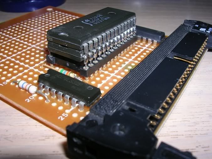
Decided to take the easy road and instead of solder dozens of wires between the two chips to link them together I would just solder them on top of each other. Such a scheme would make electronics engineers weep, but if its good enough for Sir Clive its good enough for me. Round the back is 1 pin that is not soldered to its mate - thats the CS pin which controls which chip is active on the bus at any given time.
I got this far and realised I hadn't allowed for pull up resistors on the data lines, much swearing later and I found I had a resistor network that would do the job, that came from an old microwave oven control panel PCB - don't ask. Its the long yellow thing on the PCB.
Next time I may well make my own PCB as soldering this all together was tedious in the extreme.
Actually the toughest part was working out the best layout for the chips and the resistors, there is no perfect solution and some pins were hard to get to when the thing was fully wired. This is just the data bus to the edge connector via the pull up resistors in the resistor network.

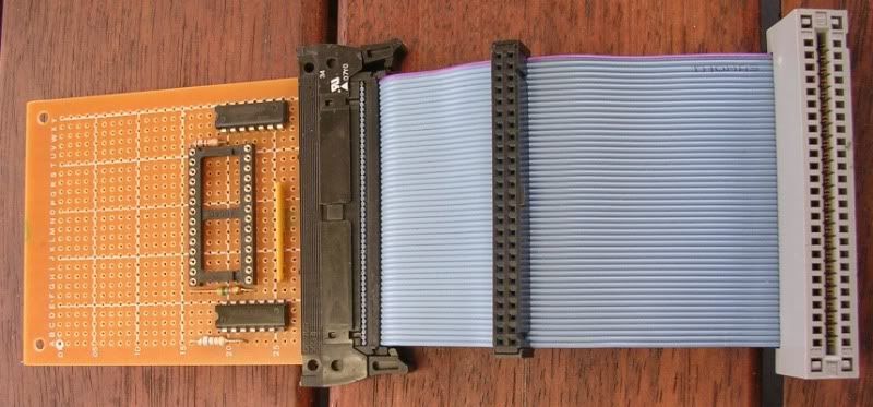
And this is when the address lines, control logic and power feeds are wired in.

All that wiring just for 64KB, imagine the wiring that's built into your 1GB DIMMs!!!

So, deep breath time, plug into the back....

Machine boots, finds new RAM, assigns the 64KB block to be master instead of the 32KB on-board, and she will now happily take a drop of Gunfright!!!

Pleased with myself I are!!!
Am going to cut the PCB in half as the top half is unused then fit it in a small case, will be about the side of a matchbox when that's done.
The one I bought was the Yamaha C5XM machine, an MSX 1 standard machine but its bolt on extra was the heart of the top of the range (at the time) Yamaha DX7 Synthesiser. Its got a honking great synth board stashed away inside which is midi compatible and has over 100 built in voices. Of course MSX software cant use that as its not standard so it has a separate ROM for the music application. They are not common tho as they didn't sell well, it was a niche market and at between 500 and 700 quid a go there were not cheap.
Anyway - having got this machine I not only wanted to play around with the synth module, I also wanted to run up some games - mainly Gunfright - my hands down favourite 8 bit game which surprisingly got an outing on the MSX.
I was to be disappointed, my MSX only has 32KB on-board, which is a drop too little to do anything useful these days. The problem is actually two-fold, firstly the fact I don't have much ram, secondly is the way MSX software is presented these days means that 32KB is less useful than it once was.
As MSX machines all had a cartridge slot, the majority of the software available these days for the emulators is in the format of a ROM dump. Even games that were never originally available on ROM have been snap-shotted and saved as binary files. This is great if you have an emulator as you just load the .rom into the systems virtual ROM slot, its also good if you have a spare ROM cart and an eprom blower as you can make a real ROM cart.
As ROMs are useful and neat, it seems all other formats have died a death, I can't find anywhere where you can download MSX software in non-ROM format. You would assume there is a way to turn the old .rom files back into wav files such as there is for many other formats. Well yes and no, spectrum and oric data files are not really ROM files, (snapshots aside), most are actually block patterns that were once on tape, when loaded sequentially the emulator is running the exact same operations that the tape loader of old was doing, only a damn sight faster. A binary ROM file contains no information about how the software was actually loaded, its just a block of information that appears on the data bus, there is no "how to load and where to start" information that was once part of the tape version of the games. These loaders are no more, stripped off by the process of dumping the RAM into a ROM file. There are what are called "wrappers" generic programs that take a ROM, and wrap a loader around it and spit out a WAV file - sounds just what I need, except there is a RAM overhead. To load a 32KB game (which was most of them) you actually need a 48KB machine as the loader needs to live somewhere and then loads the game code somewhere else), it could be a lot neater, but as the wrapper has to work for every game it cant be too clever with how it does this or many games would not work.
So I still have too little RAM even if the game was originally for a 32KB MSX machine. Even the bloody RAM checker app is 32KB and needs to be blown to an EPROM or loaded via a wrapper you need to have 48KB.
I have an old set of magazines from the 80s in a set of binders that I found in a junk shop for thruppence each, it has an inside and out review of this machine, and it states that this beast has 48K. Sadly the journalists took Yamaha's word for this and it only partially true. MSX machines led the way in misleading spec sheets. It does have 48K inside, but 16K is dedicated video RAM so really I only have 32K usable. Even machines with 64K were loudly touted as having 80KB - cheeky really.
I can find a 16KB RAM upgrade cartridge online for not an insignificant sum, but that would only take me to 48K and the game I really want to run needs 48K anyway, so once wrappedI would need 64KB again. 64KB RAM carts are rare, mainly because they were the top of the range, expensive when new and sold in low numbers. Also I think MSX is only really a loved format in some areas, most of the MSX information online is dead, tantalising links to pages that once held good info now yield only 404 messages. The hardcore MSX crowd have their upgrades that take an MSX1 machine to MSX2 standard, and add multiple megabytes of RAM plus disk drives, hard drives and all sorts of hardware that is not a great deal of use unless you are daft enough to try to make the MSX machine the only machine you use, but I don't want to get into mod scene, and it seems that most MSX machines came with 64KB, only the ridiculously expensive ones ironically had less to keep the price from going even higher.
So faced with the above problem I have decided to bite the bullet, I am going to build my own RAM expansion cartridge from scratch. I managed to find the service manual and schematic for the MSX machine I have, which luckily contains a good description of what the MSX memory manager custom chip does on system bootup. It also has a lot of very good information on the RAM subsystem and the signals presented on the rear connector.
Time for a trip to Jaycar and a rummage in my arcade scrap drawer. Oddly enough the hardest part to source was the edge connector. PCB edges as connectors were very common in the 80s, but were generally a bad idea. Connectors cost money and as you needed the PCB anyway if that could be one half of the connector then it was money saved. In the end I had to buy them online and import them from the US.
Once they arrived I took my wire cutters to an old SCSI cable I rescued from a bin at work for some unknown reason and made the cable I needed. The PCB is a small chunk of prototyping board from the local electronics shop, the TTL logic chips and right-angle edge connector is from an old arcade board and the resistors are from old PCBs I keep to scavenge parts from.
Decided to take the easy road and instead of solder dozens of wires between the two chips to link them together I would just solder them on top of each other. Such a scheme would make electronics engineers weep, but if its good enough for Sir Clive its good enough for me. Round the back is 1 pin that is not soldered to its mate - thats the CS pin which controls which chip is active on the bus at any given time.
I got this far and realised I hadn't allowed for pull up resistors on the data lines, much swearing later and I found I had a resistor network that would do the job, that came from an old microwave oven control panel PCB - don't ask. Its the long yellow thing on the PCB.
Next time I may well make my own PCB as soldering this all together was tedious in the extreme.
Actually the toughest part was working out the best layout for the chips and the resistors, there is no perfect solution and some pins were hard to get to when the thing was fully wired. This is just the data bus to the edge connector via the pull up resistors in the resistor network.
And this is when the address lines, control logic and power feeds are wired in.
All that wiring just for 64KB, imagine the wiring that's built into your 1GB DIMMs!!!
So, deep breath time, plug into the back....
Machine boots, finds new RAM, assigns the 64KB block to be master instead of the 32KB on-board, and she will now happily take a drop of Gunfright!!!
Pleased with myself I are!!!
Am going to cut the PCB in half as the top half is unused then fit it in a small case, will be about the side of a matchbox when that's done.
Thursday, November 27, 2008
ZX Spectrum Composite Video Mod
The original 48K spectrum was pared down to the very bone to keep the price low as possible, as a result many features that became standard on later 8bit machines were severely lacking, no joystick ports, no printer ports, no RS232 ports and no RBG video port. Many of these deficiencies were addressed by a multitude of 3rd party add-on interfaces over the subsequent years, yet there is still one problem facing folk who chose to use the original rubber keyed hardware today that was never properly addressed, its the fact that the only video output option is the RF (the aerial socket).
This is pain in the rear for many reasons, firstly the video quality is not as good as it could be, secondly TVs only have 1 aerial input so you have to fiddle round the back of the TV and disconnect your main aerial feed if you use it. Thirdly you have the problem of PAL type, the majority of spectrums were made with PAL I (UK PAL) modulators, if you happen to live in a non PAL I country and don’t have a TV smart enough to auto detect you are stuck with black and white.
Wouldn’t it be great if you could hook up the Speccy to one of the multitude of AV sockets modern TVs have? The Speccy didn’t have composite out because TVs of that era didn’t have composite inputs. Fast forward 5-10 years and most TVs did, but the Speccy is stuck in the past.
There is a way round this - and it is so simple it’s laughable; you need about 10 minutes, a soldering iron, and 4cm of thin wire. This modification also involves no visible changes to the case, no drilling, no cutting, and in fact the RF socket will still be the output method for the video - except it will be giving composite video out instead of RF. Happily the RF output socket is an RCA socket so you just hook up your yellow AV cable to the Speccy’s RF socket and you are away.
The trick is that the Speccy actually feeds composite video into the RF modulator in the 1st place, it modulates this to broadcast RF signals, TV is tuned to the output signal and dutifully converts it back in to composite for display. Naturally all this processing degrades the image and nowadays is totally unnecessary.
Heres how to do it - some of these photos are quite big, its hard to see what's going on when I shrank them, so I unshrank them.
Unscrew the 5 screws underneath that hold the case together. Lift the upper portion of the case off the lower and bring it towards you until you see the 2 ribbon cables attaching the keyboard to the main board. You don’t have to disconnect these but I would, you are more likely to strain them by leaving it connected while you work on the system than by removing and reconnecting them afterwards. By the way - this is the only risky part of the procedure, these keyboard membranes were never the most robust component and aged ones are probably more fragile - don’t strain or bend them ribbons.
There is one screw in the centre of the board that holds it to the lower case, unscrew this and remove the board.

In the rear left hand corner there is a metal box, this is the RF modulator, the lid is only clipped on - pop it off.
Now you can see what’s behind the RF socket, you will see a resistor standing on end in a small plastic tube, the upper leg is soldered to the central pin of the socket.

you need to unsolder that and bend the it away from the pin (Crap camera angle coming up... - you can just about see it in this shot. Tis easy to see what I mean if you have one in front of you tho).

You will also see 2 wires going into the RF box on the left hand side - one of these wires goes through a plastic insulator - that’s the video feed, clumbsily labelled V on the image.
The other one goes through a silvery nub is the +5V power feed for the modulator - we need to disconnect both of those wires. You could leave the modulator powered up but there is little point, also all the RF frequency circuitry could in theory interfere with the signal you are passing out the back in close proximity, so you might as well leave it powered off.
The 5V wire is just soldered to the upper of the board, unsolder it and bend it up out of the way as shown above. Just the video wire to disconnect, this is soldered through the board to the composite video signal line.
The video feed is soldered from beneath.

...unsolder this wire and bend it out of the way too. Make sure these 2 wires don’t touch anything or each other - you could put a piece of heat shrink insulation on both if you are enthusiastic enough.
Now Sinclair very handily chose a modulator with 2 holes through the plastic insulator on the side of the modulator, so you don’t even have to work out a way to get the wire to the socket. Pass your 4cm of thin wire through the second hole and solder the end to the central pin on the output socket. Solder the other end to where the RF box got its video input originally.
You can see the new yellow wire going from the old feed to through the second hole, also the old 2 connections detached and bent out of the way.

And that’s it - the ground on the Speccy is all common so the ground on the RF box and sleeve of the video socket is already connected up.
Double check you have wired everything as per the photos and put the Speccy back together. Connect "Der Computor" up to the telly.

Et Voila - a Speccy connected to my TV on input AV2.

Yay!
By the way – I didn’t invent this, it’s not even a recent discovery – it was described in some detail in a 1986 Crash magazine. There are also little FAQ text files from the bulletin boards of the early 90s floating around the web – but they all seem to make it sound harder than it is, and none had photos of the process which shows how simple it really is. Plus they all seem to advocate leaving the RF connected up and running a flying cable out the back of the unit – and or drilling a big hole in the case to have the feed dangling out the back – both are no-nos in my book, if I want an old system it has to be physically intact, cutting big holes is not an option, especially as it can be so damn neat as the above shows. It’s another 10 min job to reconnect the RF later if you decide you really do need it – but I can’t see why anyone would ever go back again.
This is pain in the rear for many reasons, firstly the video quality is not as good as it could be, secondly TVs only have 1 aerial input so you have to fiddle round the back of the TV and disconnect your main aerial feed if you use it. Thirdly you have the problem of PAL type, the majority of spectrums were made with PAL I (UK PAL) modulators, if you happen to live in a non PAL I country and don’t have a TV smart enough to auto detect you are stuck with black and white.
Wouldn’t it be great if you could hook up the Speccy to one of the multitude of AV sockets modern TVs have? The Speccy didn’t have composite out because TVs of that era didn’t have composite inputs. Fast forward 5-10 years and most TVs did, but the Speccy is stuck in the past.
There is a way round this - and it is so simple it’s laughable; you need about 10 minutes, a soldering iron, and 4cm of thin wire. This modification also involves no visible changes to the case, no drilling, no cutting, and in fact the RF socket will still be the output method for the video - except it will be giving composite video out instead of RF. Happily the RF output socket is an RCA socket so you just hook up your yellow AV cable to the Speccy’s RF socket and you are away.
The trick is that the Speccy actually feeds composite video into the RF modulator in the 1st place, it modulates this to broadcast RF signals, TV is tuned to the output signal and dutifully converts it back in to composite for display. Naturally all this processing degrades the image and nowadays is totally unnecessary.
Heres how to do it - some of these photos are quite big, its hard to see what's going on when I shrank them, so I unshrank them.
Unscrew the 5 screws underneath that hold the case together. Lift the upper portion of the case off the lower and bring it towards you until you see the 2 ribbon cables attaching the keyboard to the main board. You don’t have to disconnect these but I would, you are more likely to strain them by leaving it connected while you work on the system than by removing and reconnecting them afterwards. By the way - this is the only risky part of the procedure, these keyboard membranes were never the most robust component and aged ones are probably more fragile - don’t strain or bend them ribbons.
There is one screw in the centre of the board that holds it to the lower case, unscrew this and remove the board.
In the rear left hand corner there is a metal box, this is the RF modulator, the lid is only clipped on - pop it off.
Now you can see what’s behind the RF socket, you will see a resistor standing on end in a small plastic tube, the upper leg is soldered to the central pin of the socket.
you need to unsolder that and bend the it away from the pin (Crap camera angle coming up... - you can just about see it in this shot. Tis easy to see what I mean if you have one in front of you tho).
You will also see 2 wires going into the RF box on the left hand side - one of these wires goes through a plastic insulator - that’s the video feed, clumbsily labelled V on the image.
The other one goes through a silvery nub is the +5V power feed for the modulator - we need to disconnect both of those wires. You could leave the modulator powered up but there is little point, also all the RF frequency circuitry could in theory interfere with the signal you are passing out the back in close proximity, so you might as well leave it powered off.
The 5V wire is just soldered to the upper of the board, unsolder it and bend it up out of the way as shown above. Just the video wire to disconnect, this is soldered through the board to the composite video signal line.
The video feed is soldered from beneath.
...unsolder this wire and bend it out of the way too. Make sure these 2 wires don’t touch anything or each other - you could put a piece of heat shrink insulation on both if you are enthusiastic enough.
Now Sinclair very handily chose a modulator with 2 holes through the plastic insulator on the side of the modulator, so you don’t even have to work out a way to get the wire to the socket. Pass your 4cm of thin wire through the second hole and solder the end to the central pin on the output socket. Solder the other end to where the RF box got its video input originally.
You can see the new yellow wire going from the old feed to through the second hole, also the old 2 connections detached and bent out of the way.
And that’s it - the ground on the Speccy is all common so the ground on the RF box and sleeve of the video socket is already connected up.
Double check you have wired everything as per the photos and put the Speccy back together. Connect "Der Computor" up to the telly.
Et Voila - a Speccy connected to my TV on input AV2.
Yay!
By the way – I didn’t invent this, it’s not even a recent discovery – it was described in some detail in a 1986 Crash magazine. There are also little FAQ text files from the bulletin boards of the early 90s floating around the web – but they all seem to make it sound harder than it is, and none had photos of the process which shows how simple it really is. Plus they all seem to advocate leaving the RF connected up and running a flying cable out the back of the unit – and or drilling a big hole in the case to have the feed dangling out the back – both are no-nos in my book, if I want an old system it has to be physically intact, cutting big holes is not an option, especially as it can be so damn neat as the above shows. It’s another 10 min job to reconnect the RF later if you decide you really do need it – but I can’t see why anyone would ever go back again.
Saturday, November 22, 2008
Repairing Panther's Oric
Eventually I will be migrating all my old articles from my backups to the new site, but I thought I would start with the most recent/active tales of my fettling. Another member on the old site had bought an untested Oric Atmos and found that it was rather dead...
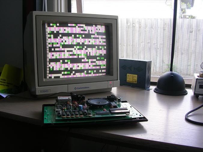
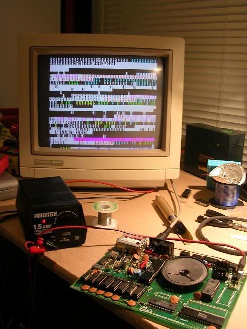
Here I sit 12,000 miles away from Panther, and yet on my desk is his Oric. Tis a funny old world, what's even more strange - is that it is working away happily beside me, probably the first time it has worked in years, decades possibly, it seems happy.
I have had it here for about 2 months, nature conspired against me fixing it a number of times, firstly my trusty Commodore 1084S decided it didn't want to be a monitor anymore, it took me about a month to work out how to convince it otherwise - monitors aint my thang. Then yesterday when I was ready to tackle it once more my bench power supply decided it wanted a change of career too. That turned out to be a manufacturing fault, am surprised it had lasted as long as it had.
Anyway - Panthers Oric arrived on these sunny shores with a nice simple fault - it did this...
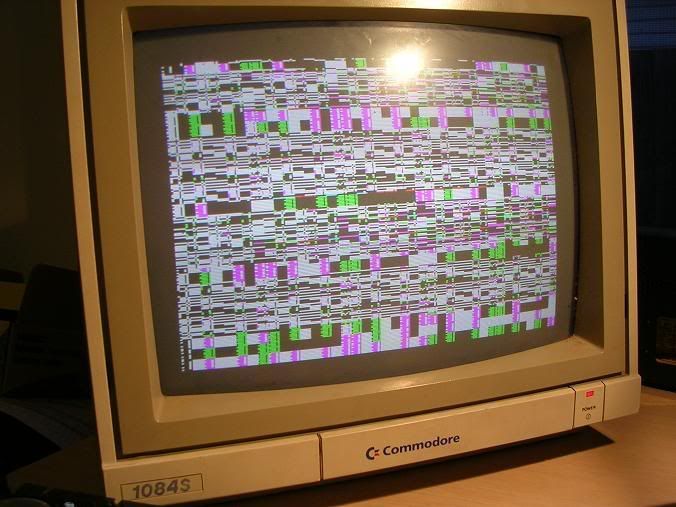
...lots of pretty coloured crap on the screen, somewhat inconsistent pattern tho.
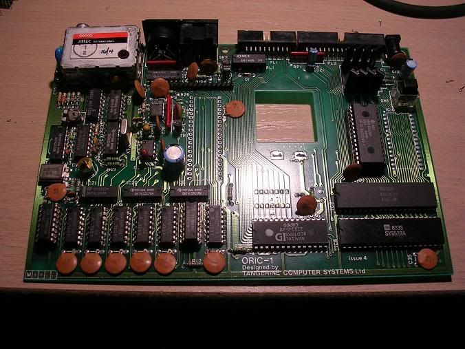
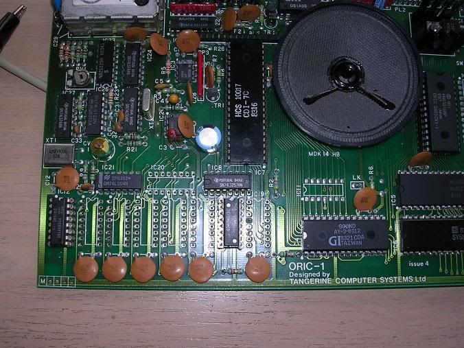
Always a good candidate for a fix, first thoughts tend to be RAM RAM RAM. Oh actually the first thought is always power supply, but as that's external you really only have to check the voltage regulator and you can move one. Tangerine computers were renowned for buying really really cheap and nasty RAM chips, they were ones that had failed the manufacturers QC, but worked just well enough to go into an Oric that didnt drive them too hard. The failure rate was alarming in the early days and its quite uncommon to see an Oric with all its original RAM, Panthers had already had 2 chips replaced. So after a quick buzz round the board with a logic probe I removed the remaining RAM, soldered in a batch from my stock and prepared to bask in the glory of a quick fix.
The speaker is a pain in the rear as its only mounted on two tags and it flops about a bit due to its weight, so that came out for a while too to make it easier to work with.
I was disappointed - even with the new RAM it was ill, similar pattered effect as before, and as I had soldered in the RAM I couldn't even swap it around a bit as now seemed to be required, the Oric is a very very fussy machine and juggling the RAM chips on my old Atmos chased away some boot up problems.
So I had to desolder all the RAM again. :(
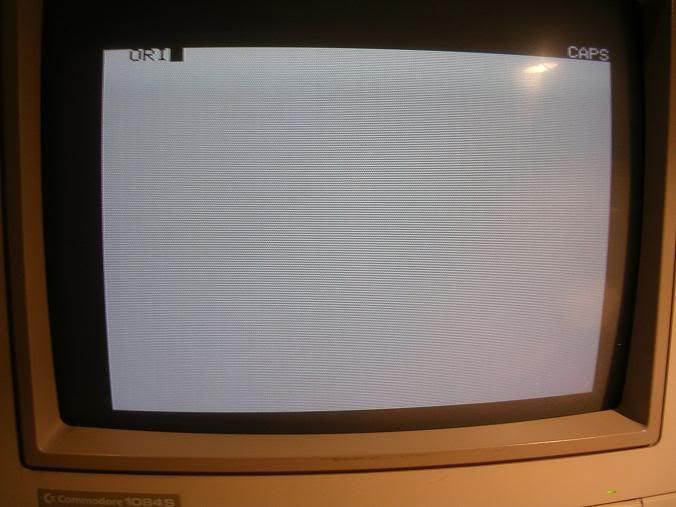
I am lucky to have another Oric here that I fixed ages ago, when that has all its RAM removed it puts up a messy black and white display on the screen that keeps resetting, presumably Panthers Oric should do the same without RAM, thus allowing comparison between the boards with RAM out of the equation. So I unsoldered the RAM from Panthers board to see what it did sans RAM - nothing similar to mine was the answer. Lots of crap on the screen, colourful tho.
I quickly dumped the eprom and compared the binary file with my Orics eprom dump, they were identical, no clues there.
At this point I was stuck, which way to go next? Orics are simple beasts and as such they either tend to work fully, or not at all, there is no half way house to give you any clues. Based on Speccy (similar architecture) faults I knew a duff ULA would give weird results, and that they are not uncommon failures, and indeed the lines on Panthers ULA were doing different things to my Oric, then again whatever was causing the fault could be driving that, and it may not be ULA at fault. Anyway - my ULA was socketed from birth, Panthers was soldered directly to the board, so I desoldered it and plopped it into my board, and was greeted by a fully working Oric - arse - so not the ULA then.
Having replaced the RAM the crap on the screen was slightly more consistent and this was reassuring, we will never know if the original RAM was good or not as I had to cut it loose to avoid damaging the board, but a consistent fault is better than a random one, RAM faults tend to look random so perhaps there was an issue there originally.
A static screen of rubbish now looked like a CPU fault - my repairs of Capcom A arcade boards has yeilded a small pile of dead Z80 CPUs and I tend to slap them into my Galaxians board to see what they do, the results are heavily dependant on what is in the associated EPROMs so the rubbish is not going to be directly comparable, but there was a fishy similarity.
So fired up the desolder station and whipped out the 6502 CPU chip.
While the board was CPUless I decided to see what the board did when powered up, surprise surprise it did a damn good impression of the main fault, it seems even with the CPU chip on board the machine is missing its CPU.
6502s were old school by the mid 1980s and none of my scrap boards date from then, any boards I do have that are older are all Z80 based. My Orics CPU was soldered in and I was not keen to subject it to a desoldering. So I hit google hoping to find a supplier or ebay seller, turns out I had one within ten feet of me, in my Commodore 64 1541 floppy drive. It also had the PIA chip that goes with the 6502 which was my other prime suspect. Both were luckily in sockets so I whipped the CPU out, fitted a socket on the Oric board and installed the CPU.
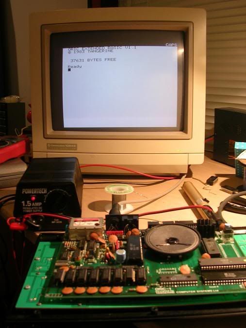
Flipped the power switch and got this....
....signs of life, the system was booting but freezing almost instantly. This was going to be either a faulty PIA chip or more RAM problems. I was planning to replace each chip 1 by 1 along the RAM bank, but infact on replacing the 1st RAM chip the system booted and beeped happily.
One working Oric, and an addition to Womble's knackered CPU pile.
Need to find a 6502 chip from my contact out West and this fella can wing its way back to Panther.
Here I sit 12,000 miles away from Panther, and yet on my desk is his Oric. Tis a funny old world, what's even more strange - is that it is working away happily beside me, probably the first time it has worked in years, decades possibly, it seems happy.
I have had it here for about 2 months, nature conspired against me fixing it a number of times, firstly my trusty Commodore 1084S decided it didn't want to be a monitor anymore, it took me about a month to work out how to convince it otherwise - monitors aint my thang. Then yesterday when I was ready to tackle it once more my bench power supply decided it wanted a change of career too. That turned out to be a manufacturing fault, am surprised it had lasted as long as it had.
Anyway - Panthers Oric arrived on these sunny shores with a nice simple fault - it did this...
...lots of pretty coloured crap on the screen, somewhat inconsistent pattern tho.
Always a good candidate for a fix, first thoughts tend to be RAM RAM RAM. Oh actually the first thought is always power supply, but as that's external you really only have to check the voltage regulator and you can move one. Tangerine computers were renowned for buying really really cheap and nasty RAM chips, they were ones that had failed the manufacturers QC, but worked just well enough to go into an Oric that didnt drive them too hard. The failure rate was alarming in the early days and its quite uncommon to see an Oric with all its original RAM, Panthers had already had 2 chips replaced. So after a quick buzz round the board with a logic probe I removed the remaining RAM, soldered in a batch from my stock and prepared to bask in the glory of a quick fix.
The speaker is a pain in the rear as its only mounted on two tags and it flops about a bit due to its weight, so that came out for a while too to make it easier to work with.
I was disappointed - even with the new RAM it was ill, similar pattered effect as before, and as I had soldered in the RAM I couldn't even swap it around a bit as now seemed to be required, the Oric is a very very fussy machine and juggling the RAM chips on my old Atmos chased away some boot up problems.
So I had to desolder all the RAM again. :(
I am lucky to have another Oric here that I fixed ages ago, when that has all its RAM removed it puts up a messy black and white display on the screen that keeps resetting, presumably Panthers Oric should do the same without RAM, thus allowing comparison between the boards with RAM out of the equation. So I unsoldered the RAM from Panthers board to see what it did sans RAM - nothing similar to mine was the answer. Lots of crap on the screen, colourful tho.
I quickly dumped the eprom and compared the binary file with my Orics eprom dump, they were identical, no clues there.
At this point I was stuck, which way to go next? Orics are simple beasts and as such they either tend to work fully, or not at all, there is no half way house to give you any clues. Based on Speccy (similar architecture) faults I knew a duff ULA would give weird results, and that they are not uncommon failures, and indeed the lines on Panthers ULA were doing different things to my Oric, then again whatever was causing the fault could be driving that, and it may not be ULA at fault. Anyway - my ULA was socketed from birth, Panthers was soldered directly to the board, so I desoldered it and plopped it into my board, and was greeted by a fully working Oric - arse - so not the ULA then.
Having replaced the RAM the crap on the screen was slightly more consistent and this was reassuring, we will never know if the original RAM was good or not as I had to cut it loose to avoid damaging the board, but a consistent fault is better than a random one, RAM faults tend to look random so perhaps there was an issue there originally.
A static screen of rubbish now looked like a CPU fault - my repairs of Capcom A arcade boards has yeilded a small pile of dead Z80 CPUs and I tend to slap them into my Galaxians board to see what they do, the results are heavily dependant on what is in the associated EPROMs so the rubbish is not going to be directly comparable, but there was a fishy similarity.
So fired up the desolder station and whipped out the 6502 CPU chip.
While the board was CPUless I decided to see what the board did when powered up, surprise surprise it did a damn good impression of the main fault, it seems even with the CPU chip on board the machine is missing its CPU.
6502s were old school by the mid 1980s and none of my scrap boards date from then, any boards I do have that are older are all Z80 based. My Orics CPU was soldered in and I was not keen to subject it to a desoldering. So I hit google hoping to find a supplier or ebay seller, turns out I had one within ten feet of me, in my Commodore 64 1541 floppy drive. It also had the PIA chip that goes with the 6502 which was my other prime suspect. Both were luckily in sockets so I whipped the CPU out, fitted a socket on the Oric board and installed the CPU.
Flipped the power switch and got this....
....signs of life, the system was booting but freezing almost instantly. This was going to be either a faulty PIA chip or more RAM problems. I was planning to replace each chip 1 by 1 along the RAM bank, but infact on replacing the 1st RAM chip the system booted and beeped happily.
One working Oric, and an addition to Womble's knackered CPU pile.
Need to find a 6502 chip from my contact out West and this fella can wing its way back to Panther.
First Steps
10 PRINT "hello world"
20 GOTO 10
BASICally thats what this post is as I am starting my own page. I used to hang around an old site that long ago was called Catharton.net and was a hangout place for folk who buy the dusty old computer crap on ebay, and spend their evenings trying to get it working again, in a nutshell people exactly like me :)
That site ended its days with the smoking ruin of the hard drive at the hosting facility and the sudden realisation that although the admin had been paying for a backed up service no sod had actually been changing the tapes, or noticing that the tape in the drive was wrecked.
That site then became a sub site of neoncherry.com, which was hacked by spammers in the last 24 hours which was the final straw.
So my articles needed a new place to live so here she is, Wombles Retro Repair Shack blog, the original format was one of a forum, which wasnt really the ideal format for my ramblings, a blog may well be.
Toodlepip!
Subscribe to:
Posts (Atom)